Hydronic System Design in HVAC Applications
Hydronic system design is a core service at HCE, particularly in water-based heating and cooling systems where we provide pipe sizing, hydraulic calculations, and pump selection. Our team ensures compliance with energy efficiency standards and seamless integration with plant and control systems.
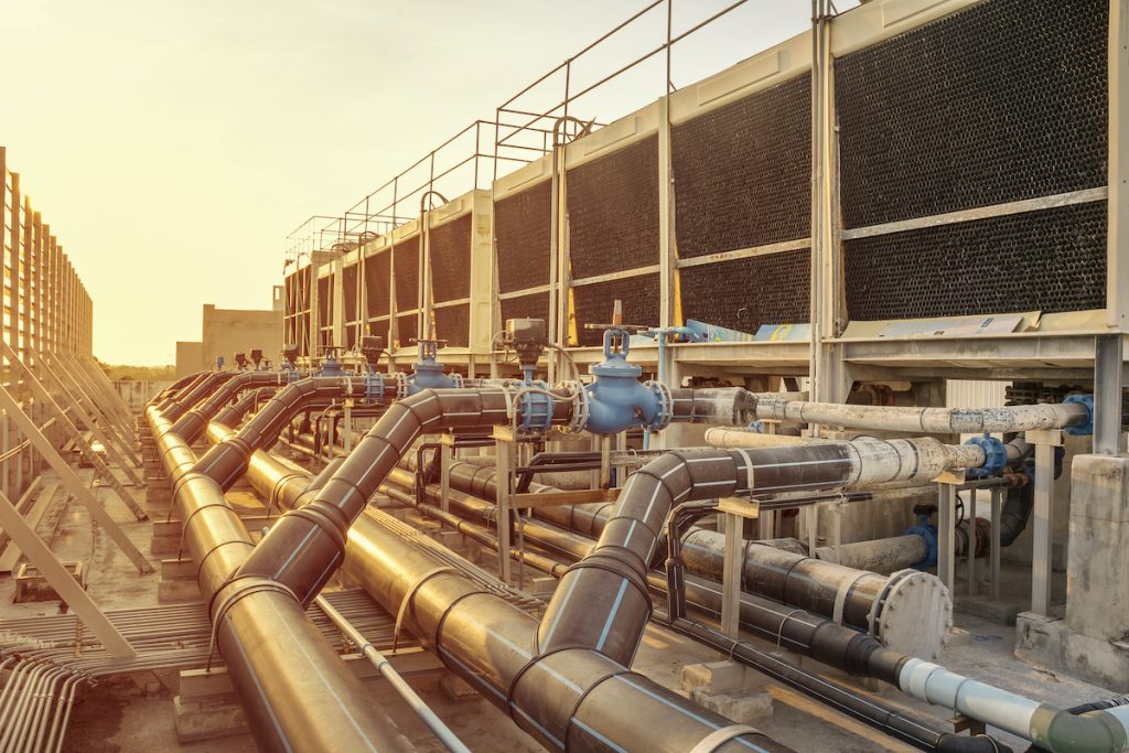
Hydronic systems use water or a water-glycol mixture as the heat transfer medium to deliver heating or cooling throughout a building. These systems are widely used in medium to large-scale commercial, healthcare, institutional, and residential applications due to their high efficiency, controllability, and ability to support diverse HVAC strategies such as chilled beams, fan coil units, radiators, and underfloor heating.
Effective hydronic system design requires consideration of fluid dynamics, thermal exchange efficiency, pump sizing, zoning, energy sources, and integration with the building management system (BMS). Designs must comply with the National Construction Code (NCC) Section J, AS/NZS 3666, and ASHRAE guidelines including Standards 90.1, 55, and 189.1.
Primary Types of Hydronic Systems
Chilled Water Systems
Chilled water systems are used to provide space cooling via a network of pipes distributing water typically between 6°C and 12°C. The chilled water is generated by central plant chillers (air- or water-cooled), then circulated to terminal units (e.g. AHUs, fan coil units, chilled beams).
Key design elements include:
- Primary-only, primary-secondary, or variable primary flow (VPF) configurations, with VPF increasingly favoured for energy efficiency and reduced pump energy.
- Pipe sizing based on flow rate and velocity constraints (<2.4 m/s in mains, <1.5 m/s in branches) to minimise erosion and noise.
- Use of variable speed pumps, differential pressure control valves (DPCVs) and pressure independent control valves (PICVs) for flow stability and control.
- Thermal insulation per Section J5 of the NCC to reduce heat gain/loss.
Heating Hot Water Systems (HHW)
Heating hot water systems distribute water typically between 60°C and 80°C, though low-temperature systems (45–60°C) are now encouraged for improved efficiency and compatibility with heat pumps.
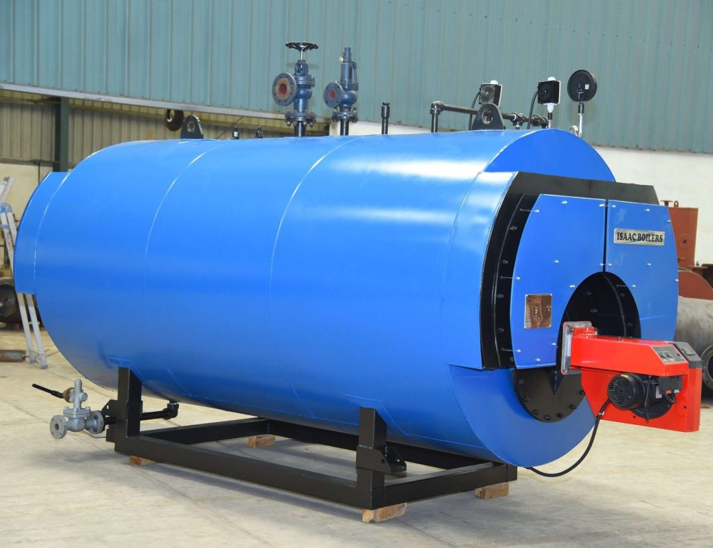
Heat is commonly generated by:
- Gas-fired boilers
- Heat pumps (air-source or water-source)
- Combined heat and power (CHP) systems
- Heat recovery from chillers or condenser loops
Design considerations include:
- Use of expansion vessels, air separators, and dirt separators to maintain system integrity and efficiency.
- Condensing boilers require careful return water temperature control (<55°C) to maximise efficiency.
- Loop configuration: reverse return systems for hydraulic balance or direct return with balancing valves.
- Redundancy via N+1 boilers or dual headers in critical facilities.
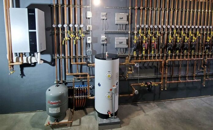
Heat Pump Hydronic Systems
Electrification of HVAC systems has driven wider adoption of air-to-water or water-to-water heat pumps in hydronic applications. These systems reduce reliance on fossil fuels and are compatible with NCC 2022’s trajectory for low-energy buildings and Green Star’s carbon reduction credits.
Design challenges include:
- Proper staging and defrost cycle control for air-source systems in winter.
- Integrating with thermal storage tanks for peak shaving and energy flexibility.
- Ensuring sufficient buffer capacity for variable load conditions.
- Limiting operating temperature to maximise coefficient of performance (COP).
Terminal Units and Distribution
Hydronic systems deliver conditioned water to a variety of terminal units:
- Fan Coil Units (FCUs): Provide localised control and zoning. Typically two- or four-pipe systems.
- Chilled Beams (Active/Passive): Offer high efficiency and quiet operation. Require precise water temperature control and dehumidification upstream to avoid condensation.
- Radiant Floor or Ceiling Systems: Use low-temperature water for heating. Require slow response times but excellent thermal comfort.
Each unit requires control valves (often PICVs), balancing valves, isolation valves, and temperature sensors integrated with the BMS for individual zone control and system-level optimisation.
Hydronic Balancing and Commissioning
Proper system balancing is essential for delivering design flow rates and achieving thermal comfort. Key techniques include:
- Manual balancing valves (commissioning sets) for static systems.
- Dynamic PICVs for pressure-independent control and reduced commissioning time.
- Flow meters, temperature sensors, and BTU meters for monitoring and verification.
Commissioning must confirm:
- Water quality in accordance with AS/NZS 3666.1, including corrosion inhibitors, biocide dosing, and regular testing
- Correct flow distribution across all circuits
- Proper sequencing of pumps and valves
- Adequate purge and air removal (via automatic air vents or degassers)
Energy Efficiency and Compliance
Hydronic systems can achieve high energy efficiency when designed and operated correctly. Consider:
- Pumping energy, managed via VSDs and demand-based control logic
- Heat loss minimised through pipe insulation and zoning
- Thermal storage to buffer load variability and reduce peak demand
- Integration with BMS analytics to optimise delta-T, identify faults, and improve part-load efficiency
The NCC mandates pipework insulation, minimised pipework lengths, and efficient plant selections (Section J5 and J6). Modelling tools like IES VE or EnergyPlus are used for JV3 compliance and thermal performance verification.